|
|
|
Applications>>PIV |
|
Lasers
for
Particle Image Velocimetry
|
|
|
|
Particle Image
Velocimetry (PIV)has evolved into one of
the most crucial flow field measurement
techniques in experimental fluid
dynamics research since the 1980s. Its
core principle involves recording the
displacement of tracer particles within
a flow field over a short time interval
and calculating the fluid's velocity
distribution using image processing
algorithms. Unlike traditional
single-point measurement techniques such
as hot-wire anemometry or laser Doppler
velocimetry, PIV enables non-invasive
acquisition of instantaneous velocity
information across the entire flow
field. This approach preserves the
integrity of the flow structures while
offering high spatial and temporal
resolution. |
|
 |
|
Laser and
Particle Imaging in PIV System |
|
|
As a revolutionary tool
in modern flow field diagnostics, PIV
has expanded from laboratory research to
broad engineering applications, becoming
an indispensable asset in fluid
mechanics studies. |
|
1.
PIV System
Components and Workflow |
|
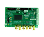
A PIV measurement system primarily comprises four components:
light source, PIV synchronization system, image acquisition system, and image
analysis system. The light source provides stable, uniform illumination to
ensure imaging quality and measurement accuracy. The image acquisition system
includes lenses and high-speed cameras responsible for capturing images formed
by the scattered light from tracer particles. The image analysis system utilizes
specialized software for real-time image acquisition, storage, and subsequent
data processing and analysis. |
|
 |
|
PIV System |
|
|
The workflow
of a PIV system involves four key stages: seeding tracer particles, flow field
illumination, image acquisition, and image processing.
The selection of tracer particles is critical.
Ideal particles should exhibit good flow-following capabilities and
light-scattering properties. Commonly used materials include hollow glass
microspheres, fluorescent microspheres, or oil fog droplets, with diameters
typically ranging from 1 to 100um. Their density should be as close as possible
to the fluid to minimize slip.
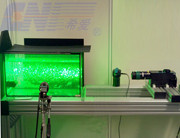
The flow field illumination system often uses
CW or pulsed lasers. The laser beam is shaped into a thin light sheet (for
2D-PIV) or a volume of light (for 3D-PIV) using Powell lenses or cylindrical
lenses to illuminate the region of interest within the flow field.
Image acquisition is performed by
high-sensitivity, high-frame-rate scientific CCD or CMOS cameras. At least two
exposures are typically required to record the change in particle positions. |
|
2. Technical Types of PIV Systems |
|
PIV
technology has advanced from initial two-dimensional planar measurements to
genuine three-dimensional volumetric measurements. Conventional two-dimensional
PIV (2D-PIV) can only obtain two velocity components (u, v) within the
measurement plane.
Stereo PIV (SPIV), utilizing two cameras at
oblique viewing angles, can extract either two or all three velocity components
from a three-dimensional velocity field (often referred to as 2D-3C or 3D-3C
measurements). Essentially, it reconstructs the out-of-plane component based on
the stereoscopic principle.
More advanced Tomographic PIV (Tomo-PIV)
employs multiple cameras (typically 4 to 6) combined with tomographic
reconstruction algorithms to achieve full three-dimensional, three-component
(3D-3C) velocity field measurement. This marks PIV's entry into a new era of
three-dimensional flow field diagnostics.
Comparison table of main PIV technology types and their characteristics: |
|
Technology Type |
Measuring Dimensions |
Advantages |
Limitations |
Typical Applications |
|
2D PIV |
2D-2C |
Simple, reliable, low cost |
No vertical component; planar
constraint |
Conventional flow
field diagnosis |
|
3D PIV |
2D-3C |
Obtain 3
components |
Still limited to planar
measurements |
Wingtip vortices, boundary layer |
|
Tomo-PIV |
3D-3C |
True 3D measurement; high seeding |
Complex system;
computationally intensive |
Complex 3D flow
fields |
|
Time Analysis PIV |
2D/3D |
High time resolution |
Low spatial resolution |
Turbulent
fluctuations, unsteady flow |
|
Microscale PIV |
2D-2C/3C |
Micrometer-level resolution |
Limited speed range |
Microfluidic system |
|
Wide-Field PIV |
2D-2C/3C |
Meter-level field of view |
Large-scale system; high cost |
Wind/water tunnel
experiments |
|
|
3. Typical Applications of the PIV System |
|
Leveraging its non-intrusive nature, full-field measurement
capability, and high precision, PIV technology has permeated various fields of
fluid mechanics research, providing essential experimental means for addressing
complex flow problems from fundamental science to industrial application
development, across macro to micro scales.
Aerodynamics Research: In aerodynamics, PIV has become a standard
tool in wind tunnel testing, used for detailed measurement of surface flow
fields and wake vortex structures around aircraft and vehicles. Unlike
traditional intrusive methods like pressure probes that disturb the flow, PIV
acquires full-field information without interference. In airfoil studies, PIV
has successfully revealed the evolution of complex vortex structures during
processes like boundary layer transition, flow separation, and dynamic stall,
providing key data for improving aerodynamic design. |
|
|
|
 |
 |
|
Aeroelastic PIV Measurements in
Fluid-Structure Interaction (FSI ) |
PIV System for Wake Flow Measurement in
Automotive Wind Tunnels |
|
|
Wind Power Generation: In the wind energy sector, PIV technology
is widely used to study wind turbine wake characteristics. The wake interference
downstream of large wind turbines can significantly reduce the overall
efficiency of a wind farm. Using large-field-of-view PIV measurements,
researchers have quantified wake recovery length and turbulent mixing properties
under different atmospheric stability conditions, offering a scientific basis
for optimizing wind turbine layout.
Ship Hydrodynamics: Research in ship hydrodynamics has long
benefited from PIV applications. In towing tank experiments, PIV systems clearly
reveal the boundary layer structure and wake field characteristics around a
ship's hull, providing visual evidence for evaluating hull resistance
performance. In a case study optimizing the bulbous bow of a container ship,
tomographic PIV technology completely recorded the interference process between
the bow wave and the hull wave at different speeds, guiding the design of an
optimized hull form that reduced wave resistance by 12%. Studies on underwater
vehicles utilize matched refractive index techniques to eliminate optical
distortion at solid-liquid interfaces, successfully measuring spatial scales of
boundary layer transition and turbulent burst events. |
|
|
|
 |
|
PIV Measurement of 3D Propeller Flow Field |
|
|
Cardiovascular flow research is a classic application of PIV technology in the
biomedical field. By constructing transparent blood vessel models and
circulatory systems with matched refractive indices, researchers use PIV to
quantify the size of vortices downstream of arterial stenoses and the
distribution of shear stress. These parameters are highly correlated with the
formation sites of atherosclerotic plaques. Time-resolved PIV further captures
the transient changes in flow field characteristics throughout the cardiac
cycle, providing crucial validation data for the design of artificial heart
valves. Recent studies have combined PIV with Optical Coherence Tomography
(OCT), enabling depth-resolved measurement of red blood cell velocity fields
within real blood vessels, achieving an axial resolution of 10 μm. |
|
 |
|
PIV Study of Aortic Valve Hemodynamics Under
Varied Cardiac Output Conditions |
|
|
4.
The Typical Lasers for PIV Systems |
|
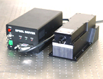
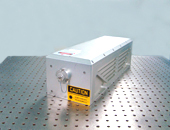
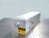
CNI provides both CW and pulsed lasers for flow
field illumination systems. The laser beam is shaped via a Powell lens to form a
thin light sheet (for 2D-PIV) or a volumetric light of specific thickness (for
3D-PIV), uniformly illuminating the target area of the flow field under
measurement. |
|
|
|
 |
 |
|
PIV CW Laser |
PIV Pulsed Laser |
|
|
Features |
|
CNI self-made high performance laser source
All accessories for PIV test system
Easy to install, uninstall and maintain
Adapt to harsh PIV environment
Provide customized solutions |
|
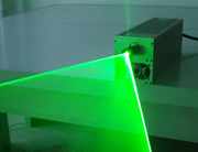
Structured Laser/ Line laser |
|
Structured laser/
Line laser
532 nm high power continue wavelength laser
|
|
|
|
LPS series Lamp-pumped Q switched structured lasers/
line lasers |
|
 |
LPS-532-A/
20~100mJ
LPS-532-S/
30~150mJ
LPS-532-L/
150~450mJ |
|
DPS series Diode-pump Q switch structured
lasers/ line lasers |
|
 |
DPS-532-A/
1~5mJ
DPS-532-B/
5~15mJ/
1~10Hz
DPS-532-Q/
1~20mJ |
|
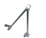
Accessories |
|
|
|
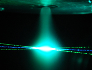
The experiment phenomena of CNI Structured laser/
Line
laser for PIV from customers |
 |
 |
 |
| Continuous laser
light sheet |
Experiment on testing flume field
with PIV
|
Experiment on testing nozzle jet with PIV |
|
|
|
|
|
|